2017 - projects
2017 - projects
Table and chairs project
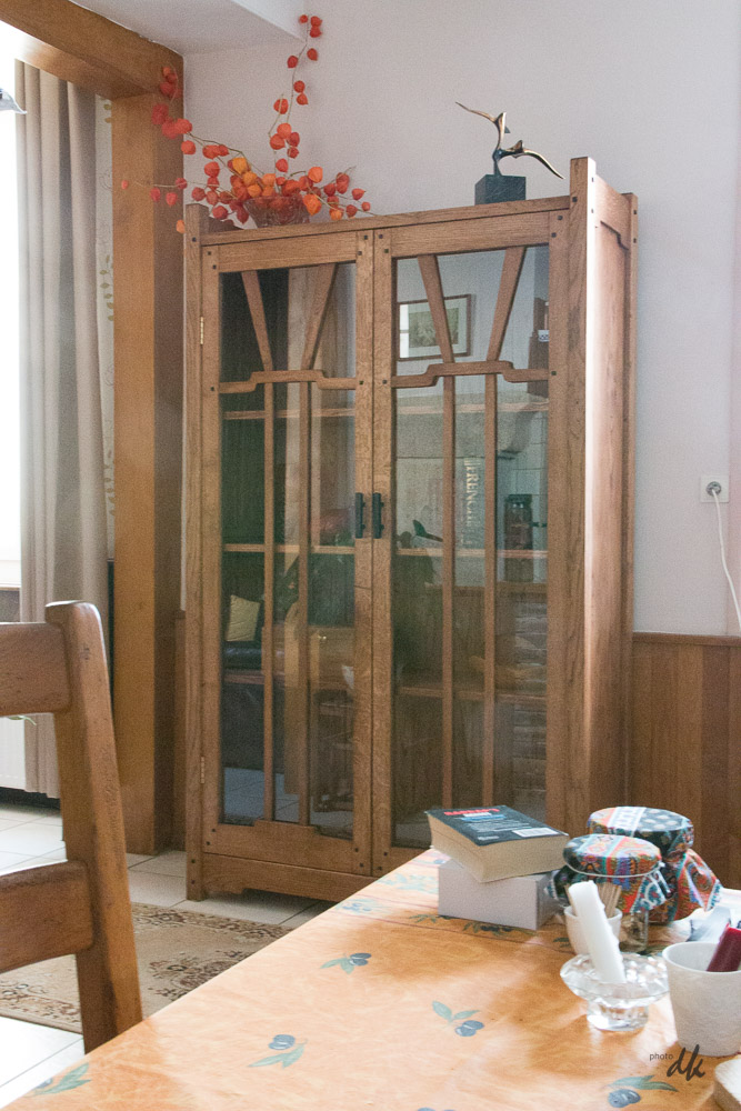
Back in december 2016 I started thinking about a project to build a table and 4 chairs for the kitchen at Rue Darnet. The 2m high Greene and Greene style display cabinet I've recently finished is just a few feet away and it really puts the old cheap pine table to shame. Hence the project which will need to be in keeping style wise.

The kitchen at Rue Darnet is fitted both sides which makes the space for the table quite long and narrow.

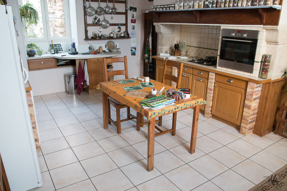
I've settled on a hexagonal table so that it can seat 4 without needing to place chairs at the sides which would block access to the kitchen cupboards. Note, this is just for casual family use, there is a dining room with table and 8 chairs (expandable to 10) for entertaining.
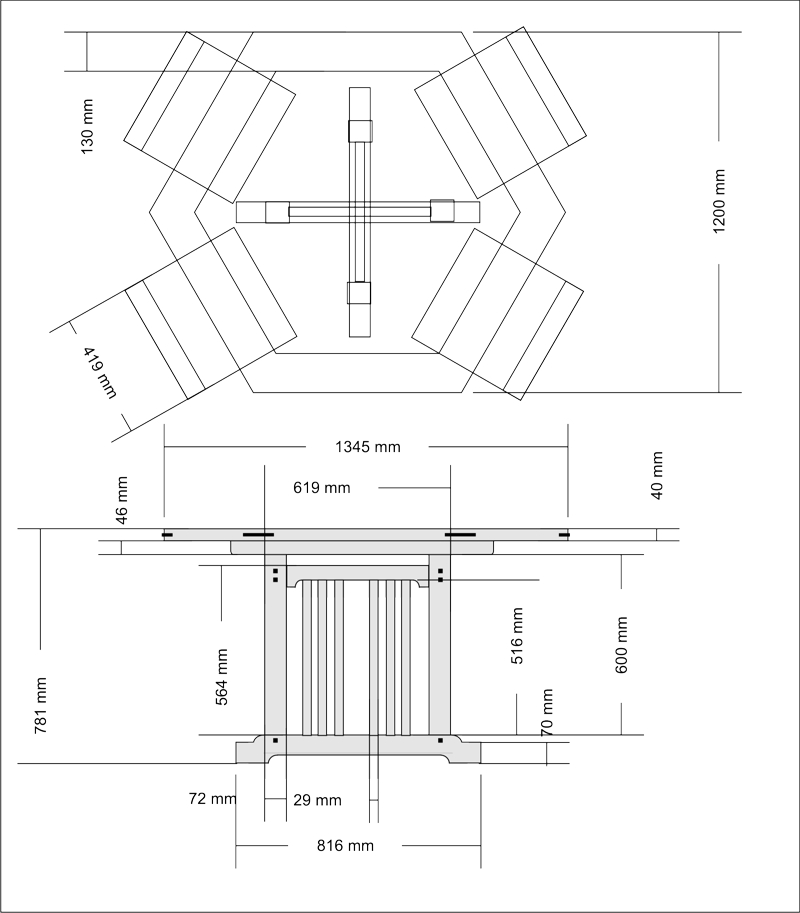
In a quiet moment just before Christmas I refined the design with precise proportions etc and added the dimensions - this is what it looks like :

Note it now fits into 1m20, leaving a tiny bit more space at the sides.
Today I plan to revisit the design of the chairs to bring them more into line with the G&G style and to reduce slightly the footprint. The original ones were quite large, seats over 50cm wide, these will need to be a bit smaller.
2017, january 13th

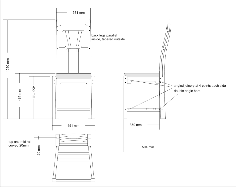
Think I need to refine the curve of the back legs, it looks a bit clunky here. Will probably make a full scale mock up.
2017, january 23rd
Not quite so cold today, started at -2°C, but rapidly warmed by the sun. Wind too cold to work outdoors, so into the workshop and made quite a lot of progress on preparing the main elements of the table.
These are the two "feet" 70 x 95mm sections and two of the legs 70 x 70 sections. All squared up, glued up ready to cut to size.

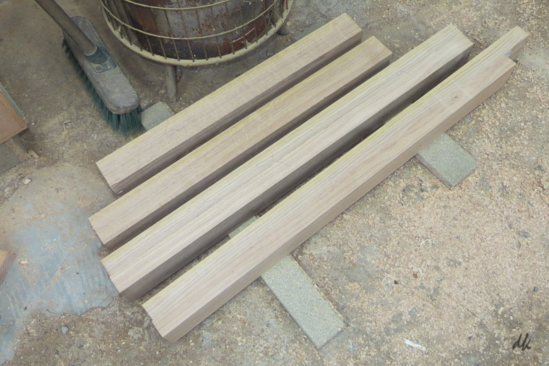
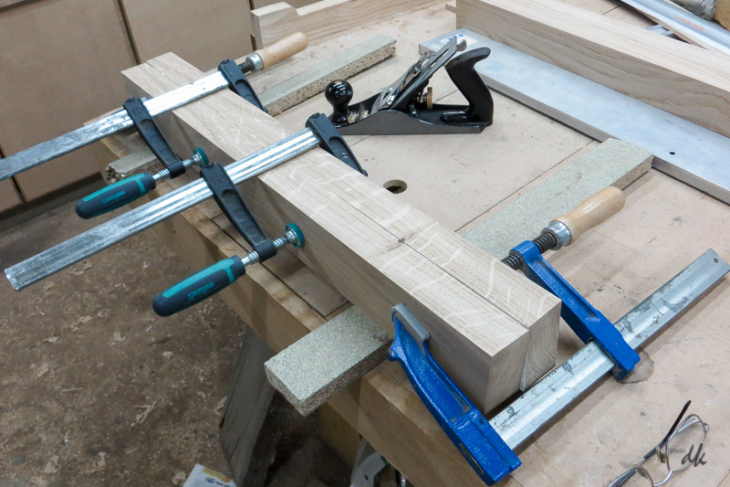
Here is the third leg in glue up:

...and here are four cross members that sit just below the top, all prepared and the cloud lift profiles roughed out by drilling the inside curve with a forstner bit, then cutting up to the hole with the band saw:

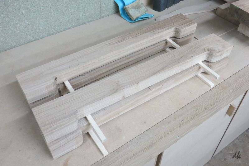
Would have been really pleased with them if I hadn't just realised that there are only two of them in the design !! Oh well, I can choose the best two !
Will glue up the fourth leg tomorrow, then plane 3 and 4 to size and start cutting mortices.
2017, january 24th
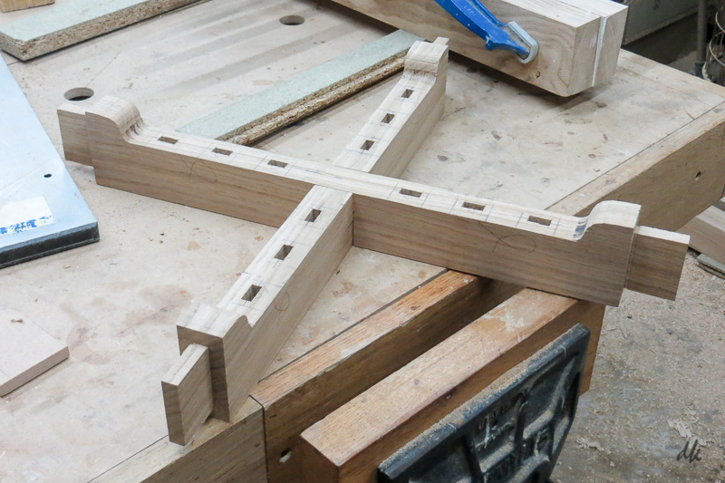
More progress today, selected the 2 best versions of the top sub frame and cut the joinery. The tenons shoulders are cut on the TS using a cross-cut sled as per my usual method, but at this stage the sides of the tenons are rough cut on the BS awaiting fine tuning when the mortices are done. The centre is half lapped.

The last leg came out of the clamps this afternoon and all 4 have been planed to exact size and cut to length.

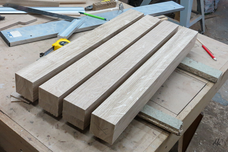
I had hoped to get into the joinery on the legs today, but the workshop is so damn cold I decided to stop at around 4pm. ![]()
![]()
2017, january 30th
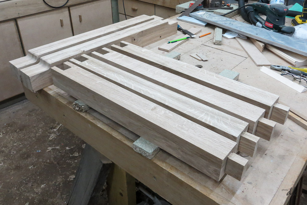 More work on the base structure for the table today. I've cut the tenons at the bottom and the sockets for the top sub frame in the 4 legs, plus started to shape the feet. The inside curves are always a bit tricky on sections as big as this, I drilled with a forstner bit and then cut up to that on the bandsaw.

The sockets were done by drilling the bottom corners, cutting up to the holes with the bandsaw, then using a coping saw to chop out the middle. Finally cleaned up with a chisel.
Drilling 80mm deep in oak with a 30mm forstner bit for the inside curve on the top of the feet was interesting to say the least. ![]()
![]()
I kept the revs right down and did a few mm at a time, then removed the bit to clear the waste and repeated. Had to wait for it to cool down at times too. Got there though ! Holes also drilled for the bottom profile of the feet, but I want to cut all the mortices before any shaping is done on the bottom of the feet to be sure that I've still got a flat and square reference surface.

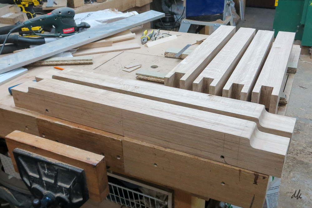
The large radius will be much easier on the bottom of the feet because it is an outside curve and can be cut on the BS.
2017, february 4th
More progress this week : mortices cut in the feet and major components carefully individually fitted for max strength. Also made the 12 vertical strips that fit between the feet and the top sub frame, cut the tenons and test fitted a few. All OK.

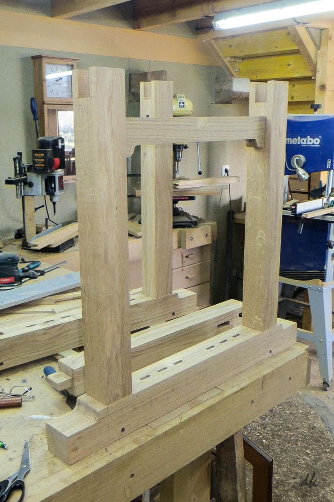

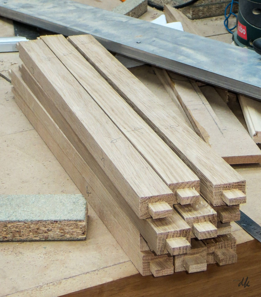
Next job is to cut the bottom cloud lift profile in the feet, then half lap them and do a trial assembly.
2017, february 7th
More progress today, got the base/plinth assembly dry fitted - I'm really pleased with it.

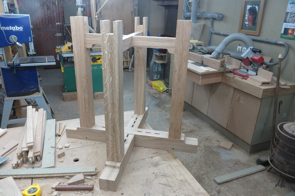
The half lap on the 80 x 90mm section for the feet was a pig to do. The bandsaw throat is not big enough to use that, my TS can cut 45mm deep, but not with the cross-cut sled fitted and I dont trust mitre gauges - so I did it all by hand with a tenon saw and a chisel. Four saw cuts in each piece to allow the waste to be removed in sections, then remove the last half mm by chiseling to the line. Got it to a just hand tight fit, needed one whack with a mallet to finally seat it. Not bad I thought.
Need to do another dry fit with the little infill/decorative uprights fitted, then it will be profiling the bottom of the feet, rounding over all the edges and cutting the sockets for the ebony pegs.
Watch this space !
2017, february 10th
It's in glue up !

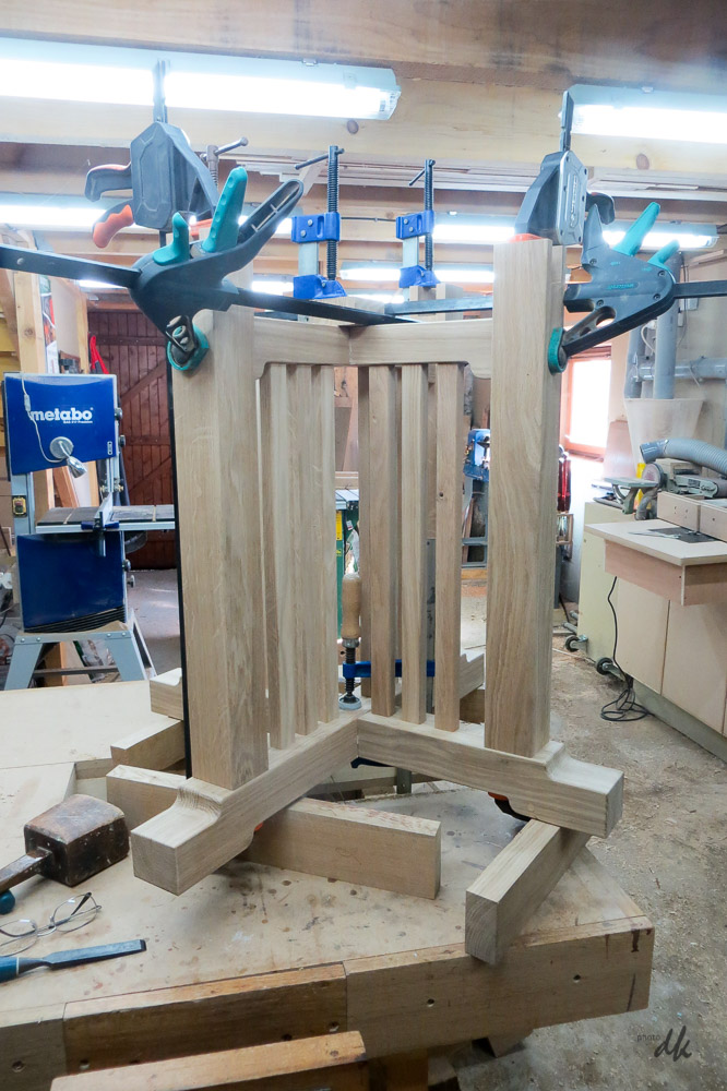
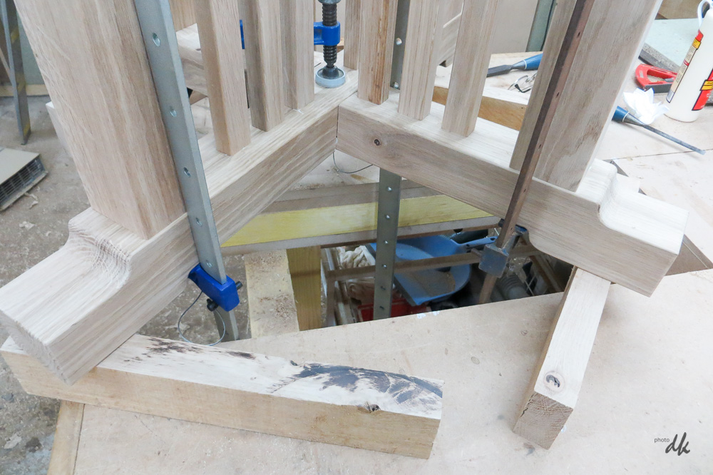
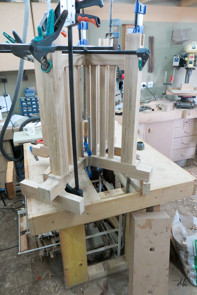
Quite a challenge : there are the 12 decorative uprights with 24 M&T joints, the four M&T joints in the cross members and four more for the legs to feet joints, plus the half lap in the middle of the cross members. That makes 33 joints all needing to be glued and assembled and clamped at the same time. I kept telling myself, "dont rush, this is no time for mistakes !".

Got there, though I was grateful for what local friends call my eccentric workbench design, as I ran out of sensible length clamps and had to use 60" sash clamps which could not go upwards because of the ceiling height, so had to go down through the bench top. Note the removable section propped against the bench.


Before doing the glue up there was a lot of sanding to be done of course and I quickly got fed up with waiting for the sander to stop spinning before I could put it down. I've seen stands based on rotating pads, but that seemed rather complicated to me, I guess they do it that way as the pad is the one common size that fits all makes of sander. Since I have only the one, I could use a simpler approach and simply make a stand that supports the handles.

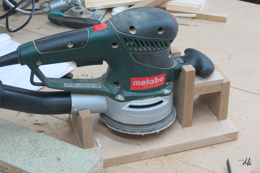
Saved me ages and improved my temper, at a cost of a few pennies worth of MDF offcuts.
2017, february 18th
Bought some big 1/4 sawn oak boards from my local sawmill for the top of the table and a load of spare for the chairs. 3.5m boards, 45mm thick and around 400mm wide. Works out to 40-50kg per board at estimated density of 0.75 or so. Something of a struggle to load and unload and even more of a struggle to cut them up.
I started by cutting them in half in the length, then tried to trim off the live edge on the bandsaw. My poor bandsaw was totally overwhelmed, it nearly fell over at one point, so I abandoned that and cut them up on blocks on the ground using a big hand held circular saw. Lots of very messy free range sawdust, but safe and effective.
Next step was to plane and thickness the rough cut sections, each around 1m by 150mm, 6 of them for the surround to the hexagonal top. So lovely to see the ray fleck emerging as the boards were planed up. Then cut to width on the table saw. Finally marked out the 60° mitres, set up the mitre gauge and cut them to length and angle. I was quite surprised when they all married up perfectly in a dry run. 12 angled cuts and not a fag paper gap to be seen when laid out ! I've always had to trim and correct jobs like this in the past, so I was really chuffed !

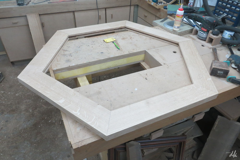
The slot around the inside is to accept the 15mm MDF central part which will have an inset oak ply panel on top to match up with the oak surround. If this was a show piece, I'd veneer it properly, but it is a kitchen table after all, so ply will do fine. By using MDF for the structure in the middle I can glue it in and avoid panel expansion issues. I tried this first on my desk top which is quite big and it has worked a treat. The surround will have M&T joints with loose tenons at each corner all with drawbored pegs to keep eveything tight.
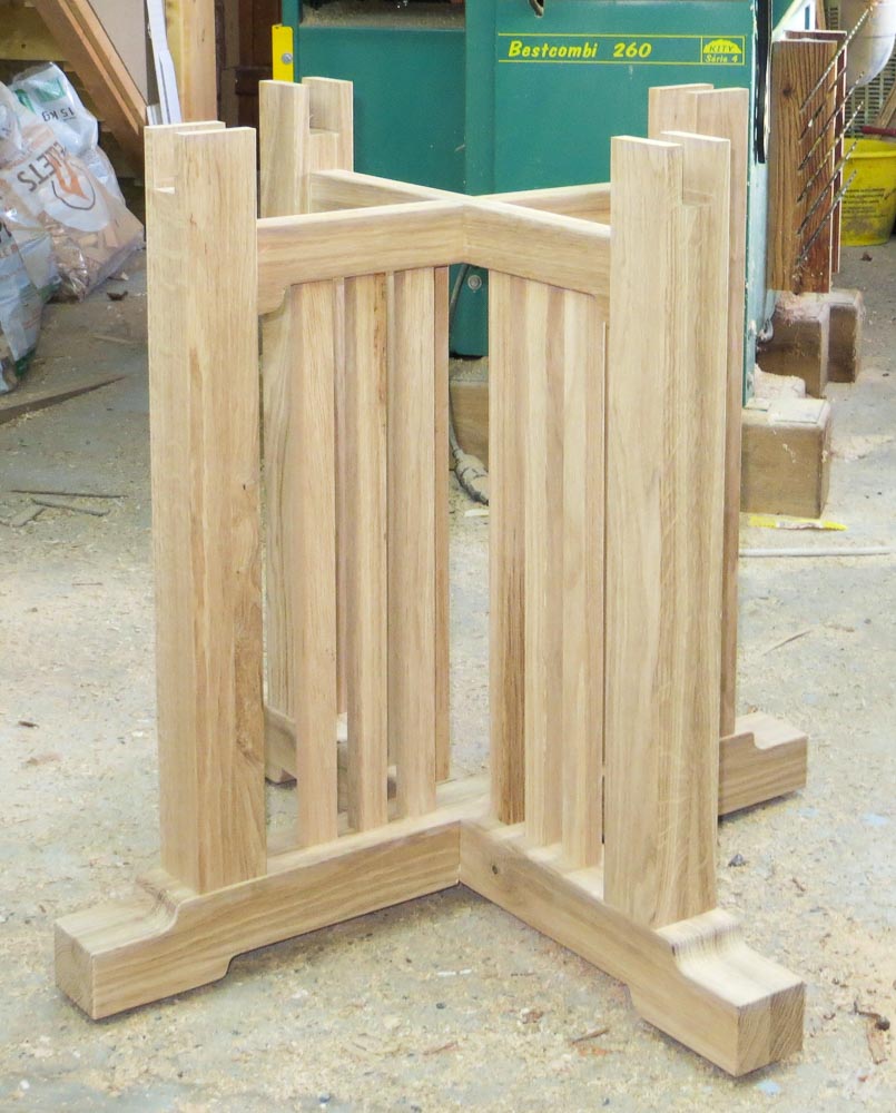
The plinth is ready to accept the top, so I hope to finish the construction this weekend - I've got all of tomorrow free since Isabelle is in Paris visiting her son, so I can get a clear run at it. Notice the slight gap under the feet. Our kitchen is tiled and Isabelle tends to slosh quite a lot of water around when cleaning it, so I've fitted small feet to keep the wood slightly off the ground - they are adjustable too as our floor is far from level.

2017, february 19th
Today I cut mortices in the ends of the 6 sections making up the hexagon. Did this with a spiral upcut bit in the router with both the work and the router supported by a router box.

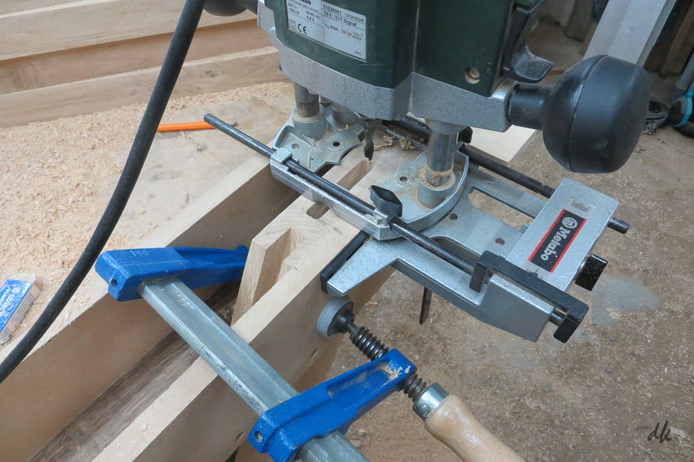
Then made a batch of slip tenons, cut the 16mm MDF into the hexagon shape to support the top. It goes together with the 16mm MDF set into a slot in the inside edge of the hexagon, just like a frame and panel door then more MDF plus a ply layer on top.

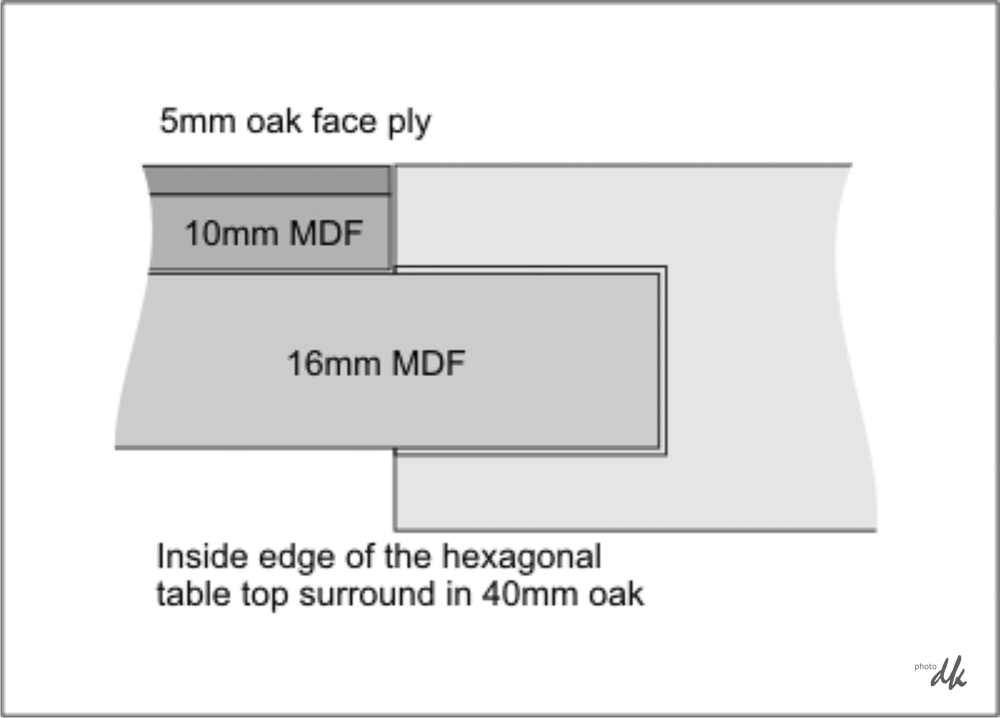
The second layer of MDF is there simply to center the 16mm panel because, without it, there would only be 5mm of the oak frame above the MDF, a bit fragile in my view. The 5mm oak face ply goes on top a bit like a veneer. Think of it as a raised panel !
Did a dry fit just before lunch to test the fit :

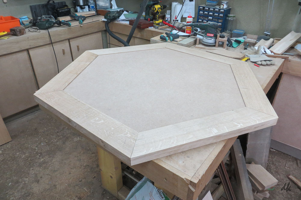
The perspective effect from a wide angle lens makes it look a bit of an odd shape, but it's actually a perfect fit, I'm delighted. Glue up this afternoon.
2017, february 20th
Last post of the day before heading for a long shower - my back is killing me !
Top is glued up, sharp corners removed, top edge profiled, but still a lot of finishing to do.

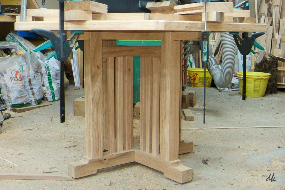
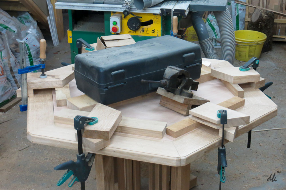
In the meantime, the oak ply is being glued into the cavity left for it in the top. A kind friend offered me a vac bag and pump, but unfortunately, the top is too big for the bag. Lots of clamps and spreaders plus some heavy weights will have to suffice !

2017, february 23rd
Yesterday I fitted ebony splines in the mitred corners of the table top and got one coat of stain on to the top and the plinth. Today I put on the first coat of varnish - normally I would go for carnauba wax over stain, but this is going to see some pretty rough wear and tear in kitchen, so a coat or three of hard poly seemed like the thing to do. This is still wet, so the colour is not even, I'm hoping it will be better when dry !
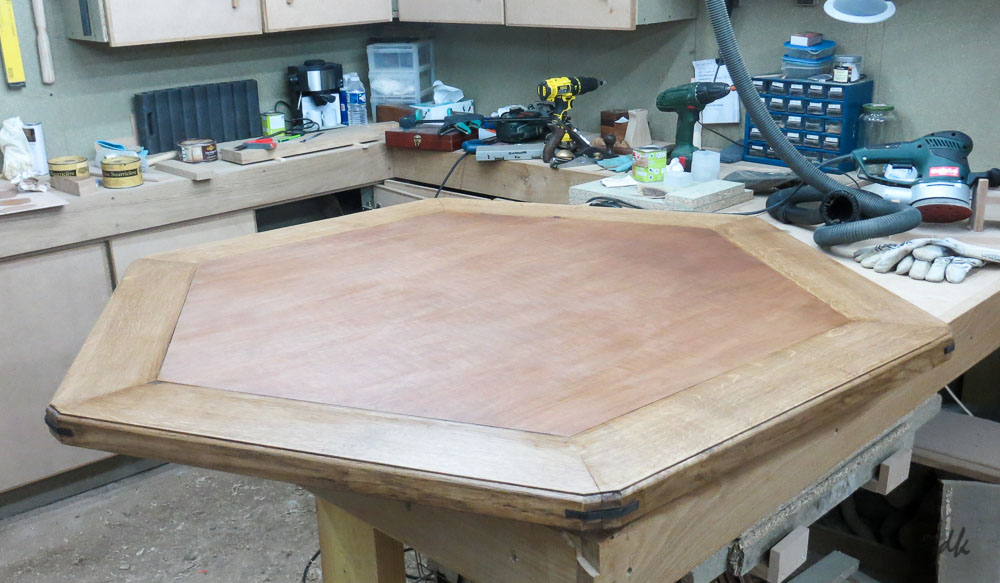
I'm increasingly convinced that the ply I bought is not oak, whatever the dealer said. The grain is not right and the colour most certainly isnt. However... I rather like the effect of a different timber in the middle of the top, so I'm actually quite pleased. Hope I dont come to regret it !!

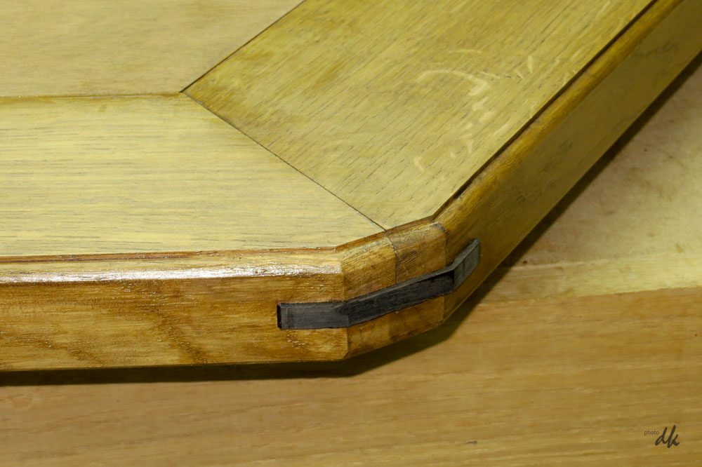
The ebony is not yet polished, the pieces are rather small to handle, so I thought it would be easier to do once they are glued into the edge - that's the next job : sanding to 240g and then waxing.
2017, february 27th
The table is finished. 3 coats of poly on all parts for protection. Shown here with one chair removed so you can see the detail of the table.

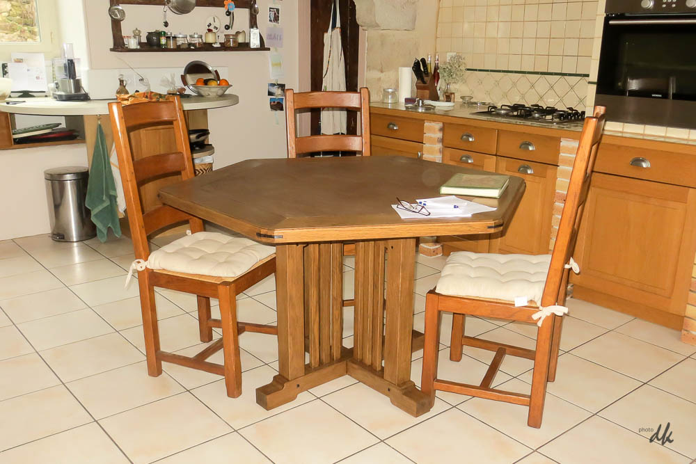
Note also that these chairs are borrowed from our dining room and they are rather biger than average. The ones I've designed to go with the table will be a bit smaller, and of course, will match in colour.

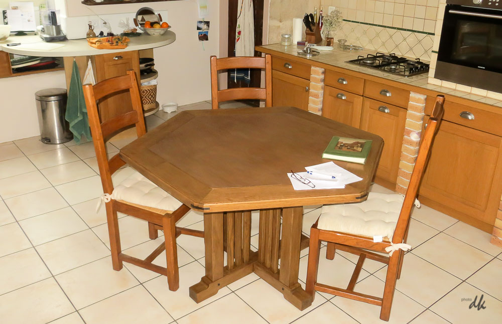

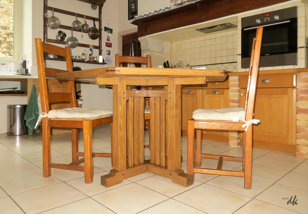
Now to finalise the curve of the back of the chairs (probably a full scale mock up) and then I can get started on milling up the parts. There are two really big boards left from the batch of oak I bought a week or two ago and used some for the table top, most of the chairs' parts will come out of that.
Re-organising the hot water system
Our house has an oil fired boiler in the barn and this also provides domestic hot water. Unfortunately, the main bathroom is right at the far end of the house, so the run for the water for the shower is huge, over 25m. The installers thought of this and put in a loop with a circulating pump so that hot water is continuously circulated right to the end of the house - it's very effective, but somewhat costly. I found out just how costly when making some measurements to find out where our electricity was going : the pump for the hot water was drawing 80W, 24/7. 700kWh for the year just for the pump in addition to the cost of the oil to keep the boiler hot and compensate for the losses from the loop.
We decided to install a "ballon", classic french highly insulated electrically heated hot water cylinder and to put this in the cellar, just below the bathroom and also very close to the kitchen - the other main user of hot water. These units are VERY well insulated, the spec on the one I've installed is that 200litres at 65°C loses heat at the rate of less than 0.1W. ie a loss of around 2Wh per day or about enough to run a 40W lamp for 3mins. Of course, for us in France, the real benefit is the cheap electricity tarif overnight.
I've kept the hot water loop, just T'd in the feed from the new heater and installed an isolating valve to separate the two, that way, in the event of power cuts, I can still run the boiler and the pump using my generator. By simply turning off the pump I found the pipes were cold so there is no significant circulation by convection for example. The other benefit was accidental : while poking around under floors to trace pipe runs I found that there was no insulation under the sitting room floor despite having been assured that there was (the rest of the ground floor was insulated, but not the sitting room) this was quickly corrected.
Installing the ballon was a rotten job as I cant quite stand upright in the cellar so I spent a day or two with my back partly bent but I'm really pleased with the results so far. I was able to turn off the oil boiler in early may and it went back on in late october : half the year.
Season 2017/18 will be a sort of test for the new arrangement, though of course consumption is not uniform year on year due to different weather, but it will give us an idea.
Lime render on the courtyard wall
2017, august 20th
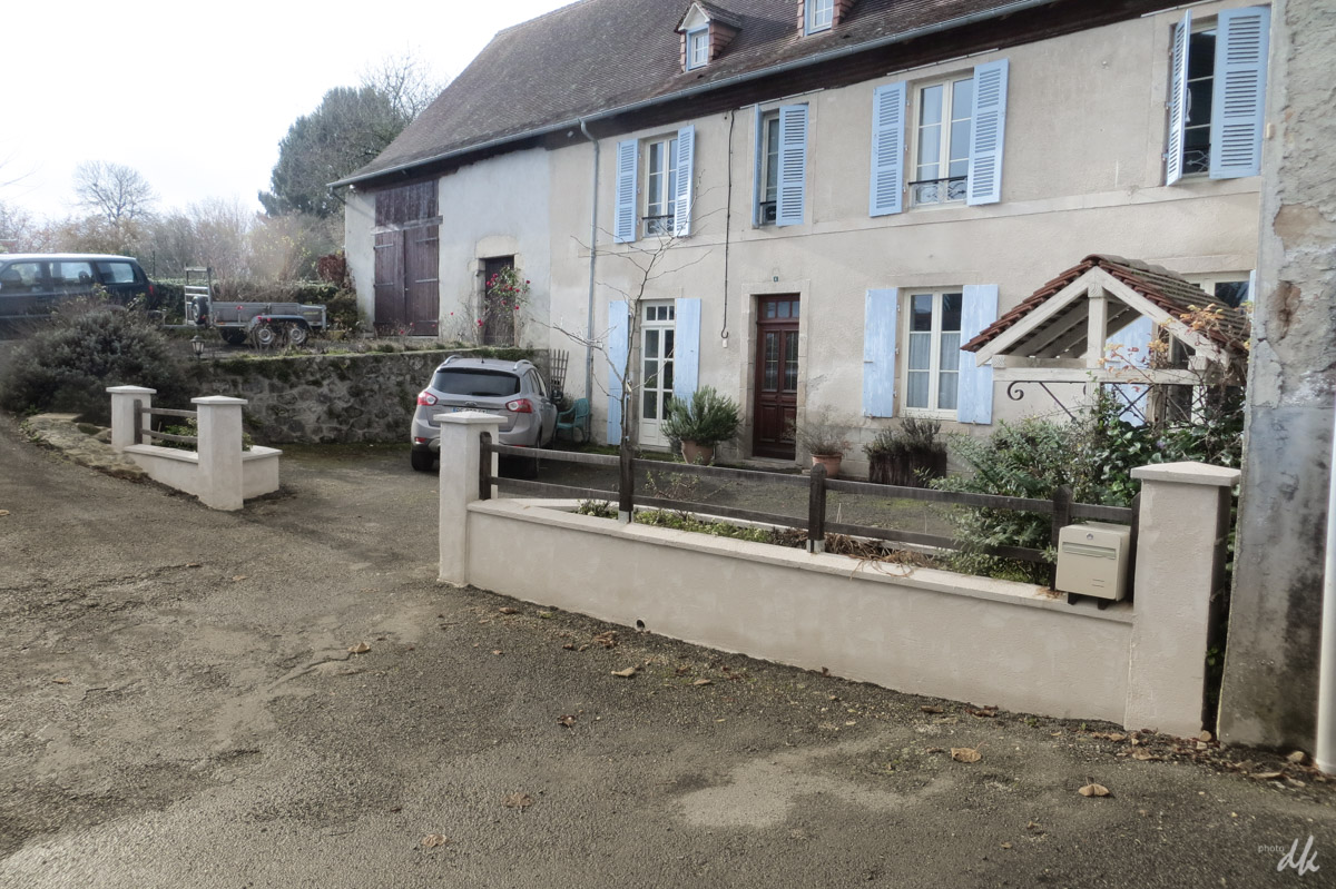
Last year I built the block wall to separate the front courtyard from the road, it all went in fine but the concrete blocks are ugly and it was always the intention to add a render - however, I've never done any rendering and kept putting it off. To say that Isabelle nagged me about it would be unjust, but in a subtle way the the subject came up once or twice and I took the hint.
Step one was to search the internet for information and I found a couple of very helpful videos that gave me the confidence to make a start. The lime render comes in 30kg sacks that you mix with 5litres of water in the cement mixer, then trowel it on. Sounds easy - it's not !! The outside corners on the pillars were especially difficult, you can buy plastic corner profiles but the colours were all wrong and the shiny corner on a matt wall looks horrible I think. The alternative advice was to fix battens and work up to those, but that meant only one of the four faces could be done each day and we had other commitments and needed to finish quickly. The first coat went on in one day with Isabelle doing quite a bit herself. Results a bit mixed, we found the colour far too yellow in relation to the render on the house itself, so back to the builder's merchant who kindly agreed to order a different colour for us and to take the remaining sacks back into stock.
Second coat went on much better, mainly down to experience from the first coat. The outside corners were mastered with a right angle trowel. Trowel marks removed by working the whole surface with a tool called a "herisson" (hedgehog) like a sort of giant surform that you use to "plane" down the surface a mm or two before it is fully hardened - worked brilliantly.
It's a bit bright and new looking compared to the house, but time and weather will cure that - not bad for a pair of total novices.

